
Curriculum[edit]
 |
Coder Merlin™ Computer Science Curriculum Data |
|
Unit: Boolean algebra Experience Name: Logic Composition (W1016) Next Experience: () Knowledge and skills:
Topic areas: Boolean algebra Classroom time (average): 40 minutes Study time (average): 180 minutes Successful completion requires knowledge: understand the use of logic composition to build complex Boolean operations from simpler building blocks Successful completion requires skills: demonstrate proficiency in using logic composition to build complex Boolean operations from simpler building blocks |
Introduction[edit]
Logic gates can be composed in the same way that Boolean functions can be composed, allowing the construction of a physical model of all of Boolean logic. Combining multiple gates enables us to build complex functionality from simpler building blocks.
Three-Input And Gate[edit]

Consider this three input AND gate internally constructed of two, two-input AND gates. Logically, this gate has three inputs and one output, regardless of how the gate is constructed internally. The truth table for this composition is:
| Inputs | Outputs | ||
|---|---|---|---|
| 0 | 0 | 0 | 0 |
| 0 | 0 | 1 | 0 |
| 0 | 1 | 0 | 0 |
| 0 | 1 | 1 | 0 |
| 1 | 0 | 0 | 0 |
| 1 | 0 | 1 | 0 |
| 1 | 1 | 0 | 0 |
| 1 | 1 | 1 | 1 |


 Helpful Hint
Implication Gate[edit]

Consider this IMPLY gate internally constructed of a NOT gate and an OR gate. Logically, this gate has two inputs and one output, regardless of how the gate is constructed internally. The truth table for this composition is:
| Inputs | Outputs | |
|---|---|---|
| 0 | 0 | 1 |
| 0 | 1 | 1 |
| 1 | 0 | 0 |
| 1 | 1 | 1 |


Implication is formally indicated by a forward arrow, i.e. , meaning, if p is true, then q is also true. As an example, consider the implication, "if it's raining then I'll carry my umbrella". There are four cases, only one of which yields false:

| Raining | Equipped with Umbrella | Evaluation of Statement | Explanation |
|---|---|---|---|
| No | No | true | It's not raining, so it doesn't matter if I'm carrying an umbrella or not. |
| No | Yes | true | It's not raining, so it doesn't matter if I'm carrying an umbrella or not. |
| Yes | No | false | It is raining, and I am not carrying an umbrella. This contradicts the implication. |
| Yes | Yes | true | It is raining, and I am carrying my umbrella. |
First Steps[edit]
This exercise relies on an external website which will enable you to easily experiment with logic gates and form various compositions with the components. The links on this wiki page will preload the relevant gates currently under discussion. For best results, open the links in a separate window so that you can continue to read the wiki while you experiment.
- The "L" indicates a Low voltage which usually represents zero or false
- The "H" indicates a High voltage which usually represents one or true
- The layout flows from left to right.
- Inputs will be leftmost and output will be rightmost.
- Clicking on an input will toggle the input from Low to High or from High to Low
- When an input is changed, the result will instantly impact the rest of the digram.
Input, Output, and an Inverter[edit]
Click on the image ("Wire and Inverter") and open the link in a different window, then return to the wiki: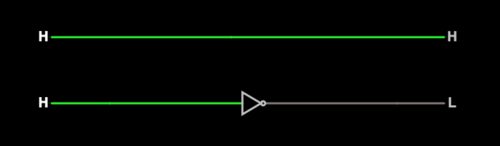
- Click on the leftmost (input) H in the top diagram which simply represents a wire.
- What happens to the H?
- Does the color of the wire change?
- How is the output impacted?
- Click on the leftmost (input) H in the bottom diagram which represents an inverter.
- What happens to the H?
- Does the color of the wire change?
- How is the output impacted?
AND Gate[edit]
Click on the image ("AND Gate") and open the link in a different window, then return to the wiki: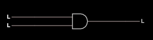
- Click on the top L input.
- What happens to the top L?
- What happens to the output?
- Click on the bottom L input.
- What happens to the bottom L?
- What happens to the output?
- Click several more times on the inputs until you're able to consistently predict the output.
Circuit Editor Basics[edit]
Starting Over[edit]
- To begin a new circuit, select
Circuit | Blank Circuitfrom the menu bar.
Inserting a Logic Gate[edit]
- To insert a new logic gate, select
Draw | Logic Gates, Input, and Outputfrom the menu bar. - Select the specific gate that you'd like to add. Your choices are:
- Inverter
- NAND
- NOR
- AND
- OR
- XOR
- Click with the mouse (but don't let go) and drag the cursor in the direction you'd like the gate to go
- Release the mouse
You can repeat the last two steps to draw the same gate again and again without needing to return to the menu.
Moving Objects[edit]
- Press the SPACE key to enter drag mode. You'll then be able to drag objects. Object with connection points which are sufficiently close to one another will be connected.
Logic Input[edit]
Logic inputs can be used to specify the input for a gate. Clicking on the "L" or "H" of an input will toggle its state.
- Select
Draw | Logic Gates, Input and Output | Add Logic Input - Click with the mouse (but don't let go) and drag the cursor in the direction you'd like the input to go
- Release the mouse
Logic Output[edit]
Logic outputs can be used to display the output of a gate. Clicking on the "L" or "H" of an output will do nothing.
- Select
Draw | Logic Gates, Input and Output | Add Logic Output - Click with the mouse (but don't let go) and drag the cursor in the direction you'd like the output to go
- Release the mouse
Wire[edit]
Wires can be used to connect inputs together.
- Select
Draw | Add Wire - Click with the mouse (but don't let go) and drag the cursor in the direction you'd like the wire to go
- Release the mouse
Text[edit]
Text can be used to add labels.
- Select
Draw | Outputs and Labels | Add Text - Click with the mouse (but don't let go) and drag the cursor in the direction you'd like the text to go
- Release the mouse
Take some time now to play with the editor and continue until you feel comfortable.
Exercise Preparation[edit]
- Construct a three-input AND gate
- Construct an IMPLY gate
Exercises[edit]
Helpful Hint
- Refer to DeMorgan's Law in W1013 Boolean Algebra
- Refer to The Special Role of NAND and NOR Gates W1014 Logic Gates
- For ALL of these exercises, you may use ONLY:
- Wires
- Logic Inputs
- Logic Outputs
- Two-input NAND Gates
- Construct your work using Falstad's Editor
- All circuits must be on a single page
- Label the page (using Text) with:
- Your name
- The date
- Begin each circuit with a Blank Circuit
- Label each circuit diagram (using Text) with:
- The name of the logic gate (e.g. "NOT")
- Save the document using the
Save As...option from the File submenu and then click on the link presented - The file contains your work for the exercise. Create a new subdirectory, J1016, in your Journals directory. Upload the file to the J1016 directory via SFTP. Be sure to push the file to your GitHub repository.
- Construct a NOT gate
- Construct an AND gate
- Construct an OR gate
- Construct an XOR gate
- Construct a NOR gate
Excursions[edit]


Consider a 7-segment LED display, as shown. The display is capable of indicating all decimal digits, 0, 1, 2, 3, 4, 5, 6, 7, 8, 9 and the hexadecimal digits a, b, c, d, e, and f.
- Constraining your output to a seven-segment display, draw each digit using only the segments provided.
- Consider a four-bit binary input, representing hexadecimal digits 0-f. Develop a series of logic gates which convert the four-bit input into a seven-segment output, such that the binary number on the four-digit input is correctly represented on the seven-segment display.
- Save a link to your engineering design in your journal.
Experience Metadata
| Experience ID | W1016 |
|---|---|
| Next experience ID | |
| Unit | Boolean algebra |
| Knowledge and skills | §10.327 |
| Topic areas | Boolean algebra |
| Classroom time | 40 minutes |
| Study time | 3 hour180 minutes <br /> |
| Acquired knowledge | understand the use of logic composition to build complex Boolean operations from simpler building blocks |
| Acquired skill | demonstrate proficiency in using logic composition to build complex Boolean operations from simpler building blocks |
| Additional categories |